

With today’s handheld and wearable devices, there is not much room left for connectors, especially in the thickness dimension. Devices in this category include the ubiquitous smartphones, as well as tablets, gaming devices, and wearables—anything that you want to be as small as possible. In devices like these, there are lots of low profile mezzanine connectors that connect displays, buttons, sensors, cameras, batteries and even antennas. It is desirable that these connections be quite reliable, but occupy the minimum possible physical volume within the device.
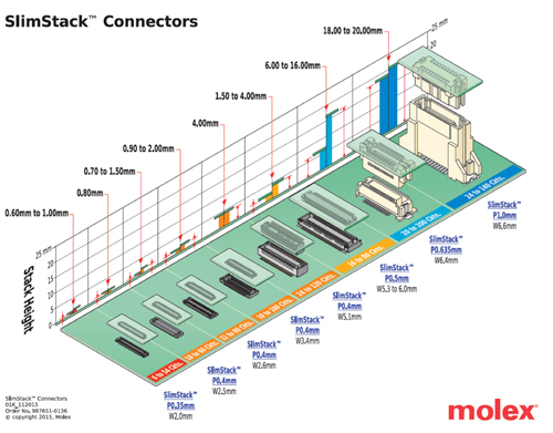
This Molex Micro Miniature roadmap shows the evolution from right to left.
A couple of solutions have evolved to meet this challenge.
The usual connector manufacturers have developed a line of “micro miniature” surface mount mezzanine connectors. These are two-piece connectors with spring beams mating with fixed beams. They are generally two-row connectors with the contacts arranged so that the mating forces are totally contained within the connector, not requiring any external forces after mating. The best designs provide excellent lead-in for blind mating and a tactile click indicating that the connector is fully mated. Over the years, this family of connectors has continuously evolved to become smaller. The contact pitch has evolved from 1 mm pitch all the way down to 0.35 mm pitch. Refinements in housing design, stamping and assembly technology now permit these connectors to be as small as 2-mm wide with a mating height of only 0.6 mm. Molex offers a version with a metal end feature that increases the robustness of this tiny gem of a connector.
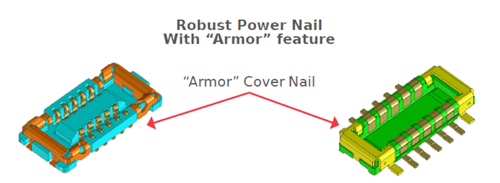
Molex 0.35 mm stack height SlimStack connector has two mating points per contact and robust metal corner features.
These low profile mezzanine connectors can be used to mate two rigid boards together, but more frequently, one half is on a flex circuit attached to the displays, buttons, etc. Designers are wise to provide support that ensures the connectors will remain mated during shock and vibration abuse, certain to happen with a hand held device. This support can be part of the case structure, or a close-by fastener that locks the elements in the mated position.
But wait! It is possible to go even lower if one uses compression technology.
We have seen many compression mezzanine solutions over the years, including Fuzz Buttons, C shaped contacts, and pogo pins, but the award for the lowest stack height mezzanine goes to the Neoconix PCBeam technology. This unique connector is manufactured using printed circuit board technology. This is not a surprise because Neoconix is owned by the PCB manufacturer Unimicron. Samtec also licenses the technology.
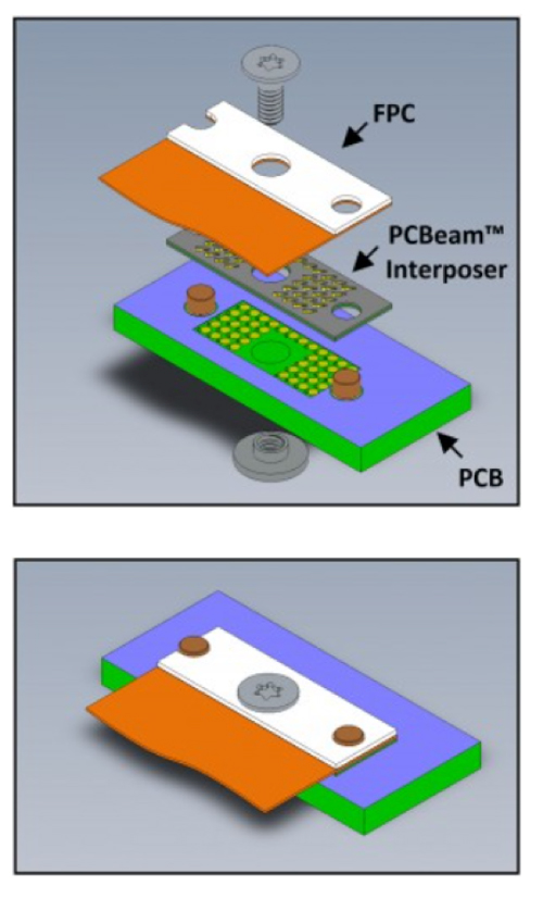
Neoconix PCBeam Interposer mating a flex to PCB.
They stamp or etch and form springs from beryllium copper sheets into arrays of contacts that are affixed to the top and bottom of a rigid board or polyimide flex substrate. Plated through holes connect contacts on the top and bottom. This structure is highly customizable, ideal for standard and especially for custom patterns. Since photo tools are used rather than complex stamping, molding and assembly machines, the barrier to creating a custom configuration is dramatically reduced. Thin is easy for this technology. Using a polyimide substrate, the stack height can be as low as 0.28 mm. Often, they are able to array the contacts around a screw hole so that the needed compression is created with a single screw; simple and sure.
The mating pad can be gold or ENIG (Electroless nickel and immersion gold.) Even at the 0.28 mm stack height, normal forces of 35 g per contact can ensure reliable performance. These super low profile connectors can have up to 200 circuits although most applications seem to be in the 20-80 circuit range. A caution: When looking at interposer technology like Neoconix, it is important that the normal force remain constant. For this reason, back up plates or rigid boards are needed above and below the interposer, adding to the total height of the assembly. A slight additional height is needed for the screw. Once it is screwed together, the assembly is completely secure and self-sufficient, not depending on case elements for support.

Neoconix Xbeam Connector and flex jumper
压缩连接器与flex电路相结合can enable many dense packaging configurations like those used in military, aerospace, communication, broadcast, test and measurement, and wearable technologies. A single board can be separated into several boards connected by flex circuits and folded up to fit tightly inside a very small volume. Often the container becomes the heat sink.
The PCBeam technology is used in mobile devices, but has many other applications as well. They are able to make compression sockets for LGA (land grid array) or multi-chip packages with more than 5000 contacts. The major applications for such large packages are very complex, expensive semiconductors that might be used in supercomputers, emulation and test systems. In these applications, the high pin count and custom footprint capabilities are more important than low stack height.
Custom configurations are also quite handy for battery connections, especially if joining several signal contacts forms the power connections. Contacts can be ganged together to enhance current carrying capacity or separated to ensure circuit isolation.
This flex jumper is configured for 48 contacts, 5 A of power, 10 Gbps electrical performance, and a total stack height including stiffener of 1.17 mm, making it well suited to connect a USB 3.1 type C connector. The footprint on the mother board is 11.25 x 7.48 mm.
So, for now, it appears that Neoconix can claim the crown for the lowest profile mezzanine or flex circuit solution with metal contact beams. Let’s see what R&D and creative engineers might bring us in the future.
The postWhere are super low profile mezzanine solutions used?appeared first onConnector Tips.
Filed Under:Connector Tips


