

By Joyce Laird, contributing editor
Understanding design challenges
Most of the couplings on the market today are either partially, or entirely, made of metal. Since metal is such a good electrical conductor it can be a challenge for the design engineer to find a suitable product to serve as a flexible coupling for transmitting torque and yet not transmitting electrical current.
Looking at options
Randy Kingsbury, Vice President, Sales & Marketing for Helical Products Company explains that there are several options available for specifying an electrically isolating coupling, however there are numerous key factors to consider before making a final selection.
“As with any coupling selection the engineer needs to consider the shaft diameters, attachment method, torque being transmitted, torsional stiffness required for accurate performance, plus the amount of current and/or voltage needing to be isolated,” he says.
Option 1: Non-metallic coupling
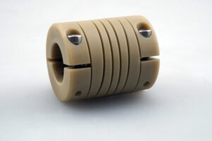
Non-metallic coupling.
“The best choice for total electrical isolation is obviously a non-metallic coupling, but those types are couplings are limited in performance capabilities. The drawback is that because of the low modulus of elasticity and low yield strength of any non-metallic material that would be suitable for a flexible coupling, any part manufactured would have a very low torque rating and high torsional flexibility. These characteristics are usually counter to what a design engineer is seeking.”
“Another major problem with a non-metallic coupling with its inherent low strength, makes fastening the coupling the shaft a problem. Threads can easily strip out before enough clamping force can be applied to a cap screw or downward force applied by a set screw, Kingsbury adds.
Option 2: Multi-piece coupling
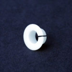
A dielectric insert.
The next option for specifying a flexible coupling for electrical isolation is to use a multi-piece coupling where the flexing element is non-conductive.
“A good example of this is the jaw type coupling,” says Kingsbury. “In this case the hubs are made of metal (either machined or cast) so the problem with attachment strength is eliminated. An insert between the hubs can be selected that is created from a non-metallic elastomeric compound ranging from rubber to urethane or other moldable materials.”
“An advantage of this jaw type coupling in electrically sensitive application is that the elastomeric insert can be selected with differing durometers which allow better tuning the coupling to the
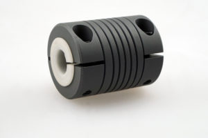
Dielectric insert fully inserted into the coupling.
operational requirements of the application.”
“Although this type of coupling provides good electrical isolation it is still bound by the potential drawbacks of any multi-piece coupling,” Kingsbury warns. “Over time it is possible for the spider to wear and backlash is induced into the system, which will affect its accuracy and smooth operation. Because of this wear this type of coupling would not be a good choice in an operational environment where contamination from wear of the elastomeric spider would be a concern.”
Option 3: Work around the issue
Kingsbury says that the third, and often the best, option for providing electrical isolation with a flexible shaft coupling, is to select the best suited coupling as if electrical isolation is not a concern and then use a non-conductive bushing to isolate either one or both shafts from the coupling.
“This requires ordering the coupling with bores larger than the shafts and then machining, or ordering, a dielectric insert to separate the bore and shaft,” he explains. “To make this work also requires a coupling with a clamp style attachment so the compressive force can prevent slipping between the bushing and shaft, or bushing and coupling.
“Torque transmission may be limited because of the low coefficient of friction between the insert and mating parts. A set screw attachment will not work because it would require so much tightening torque to hold the coupling and bushing that it would likely damage the insert and result in metal to metal contact between the coupling and shaft.” He adds.
Evaluating all the options
In conclusion, Kingsbury says, “Overall there are many ways to solve the challenge of using couplings in electrical isolation applications. These are only a few of the main methods. Whether choosing any of the examples explained above, or attempting any other solutions, it will always be necessary for the design engineer evaluate the option thoroughly, as well as investigate the voltage/current being isolated to ensure there is sufficient resistivity provided by the isolating material selected.
Helical
www.heli-cal.com
Filed Under:Coupling Tips


