

With motion control applications, a PID or比例 +积分 +导数控制器通常是使用调谐或在商店地板上的试用过程实施的。但是,运动控制系统的建模允许对PID控制器项的分析推导。
由汤姆·拉迪根(Tom Radigan)|高级运动概念公司
对运动控制系统进行建模始于框图。图显示了此模型包括几个不同的元素。闭环运动控制系统的那些包括输出位置C(s),该位置c(s)不断使用反馈进行监控……在这种情况下,是线性编码器。
求和结,反馈是减去from the target position R(s) and the result is an error E(s) that is sent to the PID controller. In motion-control applications the PID controller operates in discrete time with a sampling period. Every sampling period, the digital controller takes the error signal and produces an output within ±10 volts. It does this using a zero-order hold and a DAC or digital to analog converter. The zero-order hold refers to the process of sampling the signal and then holding between intervals; this introduces a delay into the system.

这是一个闭环运动控制系统,其输出位置C(s)不断使用反馈进行监控……在这种情况下,是线性编码器。
然后,数字到模拟转换器接收PID控制器的输出,并将其转换为模拟电压。放大器采用电压信号并产生电动机的输出电流。线性执行器采用输出电流并产生线性力,该线性将转化为输出位置。线性编码器通常使用计数测量的正交信号提供对控制器的位置反馈。尽管模型是离散和连续时间元素的混合物,但让我们在连续时间执行分析以简化模型。
实际上,运动控制系统的建模使用拉普拉斯变换在S域中进行,以得出传输函数。理想形式的PID控制器的S域传输函数是:
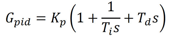
kp是比例的收益,t一世是整体时间常数,td是导数时间常数。让K。一世成为整体收益和Kdthe derivative gain:
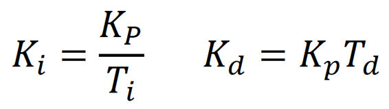
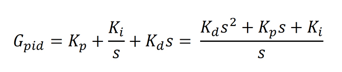
使用这些术语,可以实现PID控制器的并行形式:
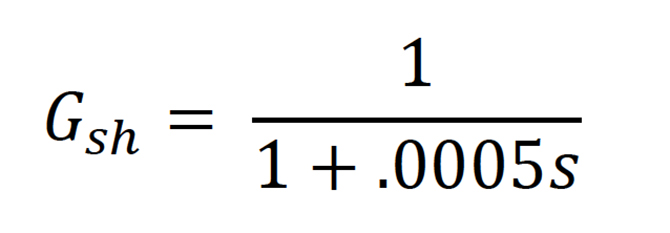
零级保持传输函数是带有采样周期τ的一阶低通滤波器sh/2:
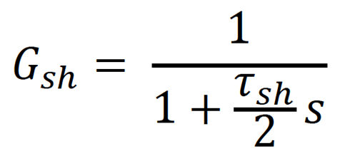
让τsh= 0.001秒:
The DAC is modeled as a constant gain with n bit resolution:
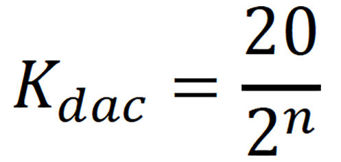
Letting n= 14 bit:
![]()
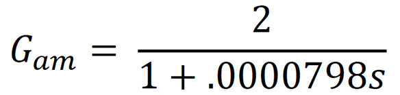
放大器建模为恒定增益k是。考虑到有限的带宽fb添加了一阶低通滤波器。滤波器的时间常数为τ是:
![]()
让K。是= 2安培/伏特和Fb= 2,000 Hz:
线性执行器被建模为增益kF- 线性运动力常数加上f = mA的拉普拉斯变换。在这里,A是加速度,M是执行器和有效载荷的质量。该模型没有摩擦,因为系统将使用空气轴承。执行器传输函数具有输出(仪表)和当前(AMP)的输入:
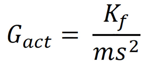
让K。F= 8.9牛顿/放大器,M = 00.5公斤:
![]()
The linear encoder is modeled as a gain Ke. If the resolution of the linear encoder is 0.1µm/count, then the linear-encoder gain is Ke=每米10,000,000。
从零级保持到线性编码器的所有元素的乘法称为开环函数 - gp(S)H(S)。此频域分析中的开环函数是:
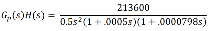
开环函数对正弦输入的响应称为其频率响应。频率响应可以通过在开环函数中用JΩ替换S来计算频率响应。那么稳态响应是:

Where the difference between the output and input sine waves can be described by two parameters — magnitude M and phase φ. Magnitude measures the amplitude ratio and phase measures the phase shift. The magnitude and phase can be determined with a calculator for low-order systems. For higher-order systems, the magnitude and phase can be determined using technical computing software such as Matlab or GNU Octave.
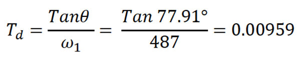
首先 - 我们需要计算G的阶段p(JΩ1)h(jΩ1)或arggp(JΩ1)h(jΩ1)。这是在指定频率ω处的每个开环函数的每个元素的相移的添加1。必须选择指定的频率……让我们选择487弧度/秒:

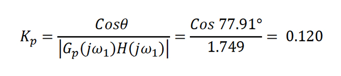
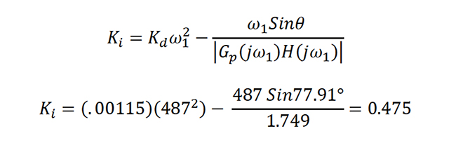
Second — the magnitude |Gp(JΩ1)h(jΩ1)计算为1.749。
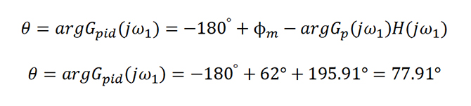
第三 - 我们需要指定相位边缘φm(或稳定性)系统。相位边缘是在频率ω处的实际相位和-180°之间的差异。1增益等于0 dB。我们选择一个62°相距。
第四 - 然后可以找到PID控制器的参数或相移贡献:
θ的大小必须小于90°……现在我们可以解决PID比例增益:
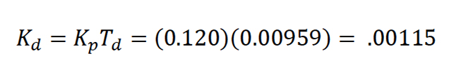
解决派生时间常数:
解决PID导数增益:
 最后,解决PID积分增益:
请注意,这些计算不是系统稳定性的保证。工程师必须使用闭环传输功能检查系统响应对步骤输入的响应……并且还必须使用Nyquist图检查系统稳定性。最后,要匹配PID增益与控制器,PID的形式必须相同。例如,运动控制器PID必须采用合适的或平行的形式。否则,收益将不会计算为适当的值。有关更多信息,请阅读反馈控制系统,第五版 - Charles L. Phillips和John M. Parr。
提交以下:线性运动提示,,,,编码器•线性


告诉我们你的想法!