

力矩限制器是机械和机电al power-transmission devices that protect machine sections (or workpieces they’re servicing) from overloads, crashes, and damage from jams.
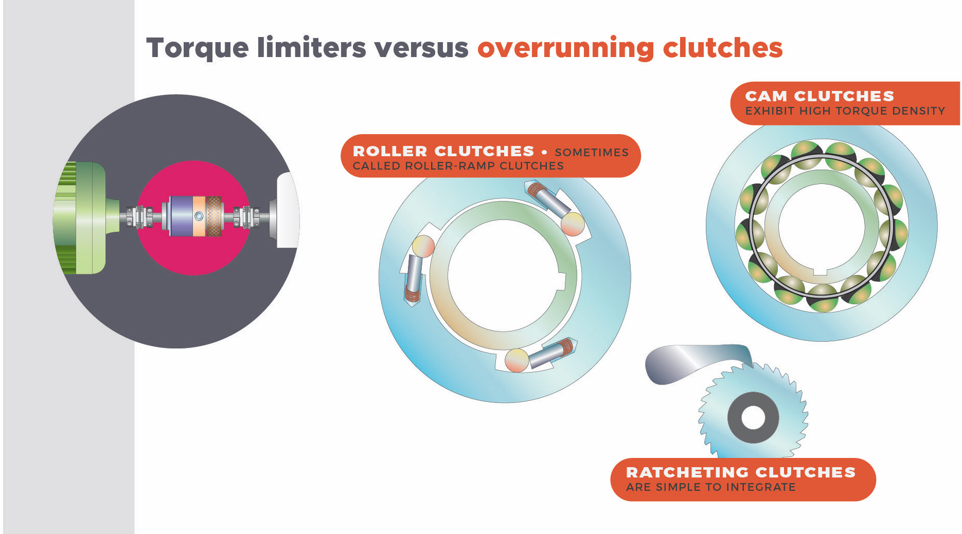
Torque limiters work either by slipping or completely disconnecting the drive from the driven load. Some torque limiters of the former type (especially those employing friction plates) are also calledslip clutches. In other contexts, torque limiters are sometimes called overload clutches.
Related components include those classified as mechanical overrunning clutches and based on wrap-spring, roller ramp, ratcheting, and cam action for engagement in the axis’ drive direction. These include backstop and freewheeling clutches, which transmit torque in the drive direction and (in the backwards direction) lock and freewheel, respectively.
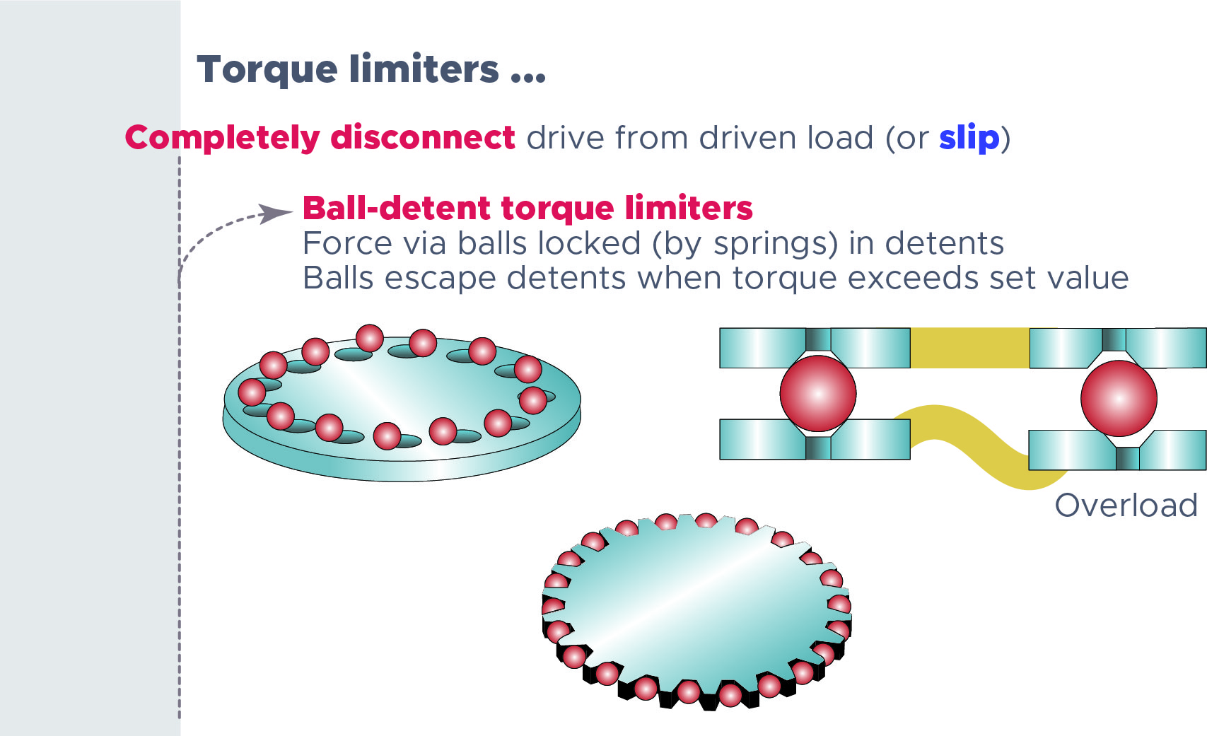
Torque limiters that employ complete disconnection include several subtypes.
Ball-detent torque limiters通过arra传播力ys of balls locked (by springs) in detents. These single or multi-position torque limiters clutch attached load by letting the balls escape their detents when drive torque exceeds that to overcome the spring set. Roller-detent torque limiters work much the same way as ball-detent varieties — by wedging between the torque limiter’s inner and outer races. These torque limiters can require manual reset, or they can reset automatically. If a multi-position model, detents are spaced every 30, 60, 90° or other interval to serve slow-speed axes that can’t tolerate a long slow wait for reengagement.
In shear-pin limiters,the drive and driven side each secure a disc … and these have one or more pins embedded in their faces In this way, the pins bridge the discs and then break when the assembly exceeds design torque. As with ball detents, these releasable shear-pin torque limiters completely release. One caveat is that these limiters can’t transmit torque to power the axis through jams if that’s appropriate for the system design. In some cases, this can make for nuisance disconnections.
Permanent-magnet synchronous torque limiters还采用双圆盘安全地固定在一个驱动d drive sides of the drivetrain. These discs have mating magnets on their faces. Torque is transmitted through the airgap between the discs — even through tank and vacuum-chamber walls in some cases. The torque limiters deliver quick response but can exhibit backlash.
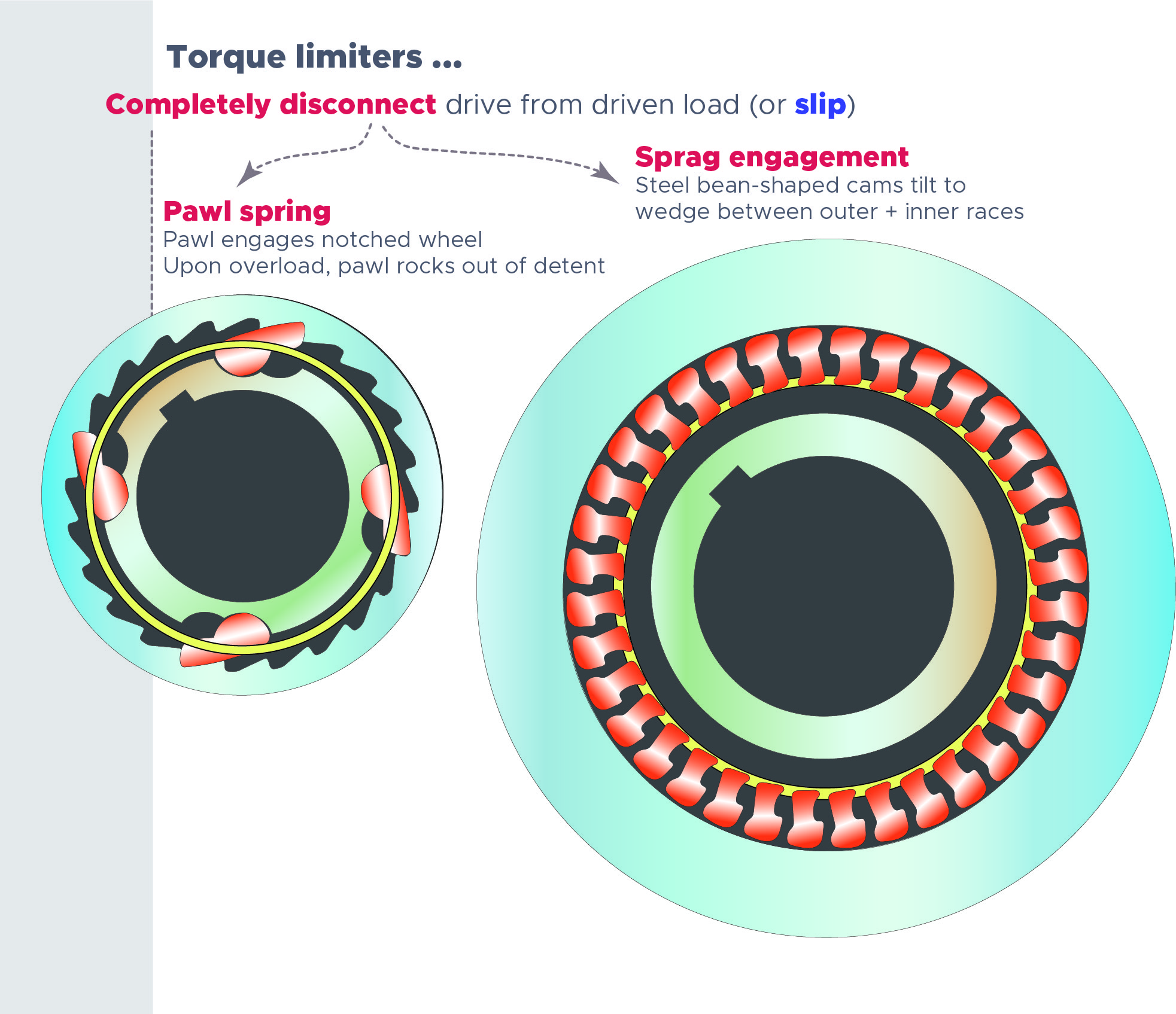
Spring-loaded (or pneumatically loaded) pawl-spring torque limitersinclude a spring-loaded pawl that engages a notched wheel. Upon overload, the pawl rocks back out of its detent to release the load until manual or automatic resetting.
Sprag-engagementtorque limiters use steel wedges that tilt during operation and wedge themselves between the assembly’s outer and inner races. In some designs, overtorque can induce sprag overtipping and load release.
In contrast with these torque limiters that work by complete disconnection, slipping torque limiters dissipate power as heat and do not need to be reset upon load correction.
Magnetic-particle torque limitersare one such type with a hollow shaving-filled housing between a driven and drive side of the assembly. The loose nickel, iron, or chromium shavings lock into chains (along magnetic field lines) upon the application of current. Torque settings can be static or dynamic (for changing values) as the application requires; there’s a roughly linear relationship between current through the windings and the magnitude of torque transmission.
Magnetic-hysteresis torque limitersalso use current to create a magnetic field for coupling. Magnetic particles within the drag cup and pole assembly continually flip to maintain magnetic alignment with the assembly’s applied field. Cup hysteresis causes mechanical coupling with losses for flux changes that lag those of the pole assembly (for smooth power transmission). Eddy-current clutches are similar but include a nonferrous (conductive yet nonmagnetic) output rotor cup. Magnetic flux between this subcomponent and a cup on the assembly’s drive side induces eddy currents and a field; the latter aligns with the coil-applied magnetic field to generate coupling torque by eddy-current field distortion.
Friction-disc torque limitersuse friction contact between mating discs to transmit power — and work much like friction-disc clutches in that overloads cause slipping between the discs. Friction-disc torque limiters excel in applications requiring continual running and moderate adherence to a safe-torque setting for safety. When mounted onto motor-driven machines, these torque limiters allow axes to power through partial jams using motor inertia to continue application of torque. That prevents nuisance stops during momentary load increases … though during true overloads and inertial shock loading, the torque limiter slips continuously to protect the system from damage.
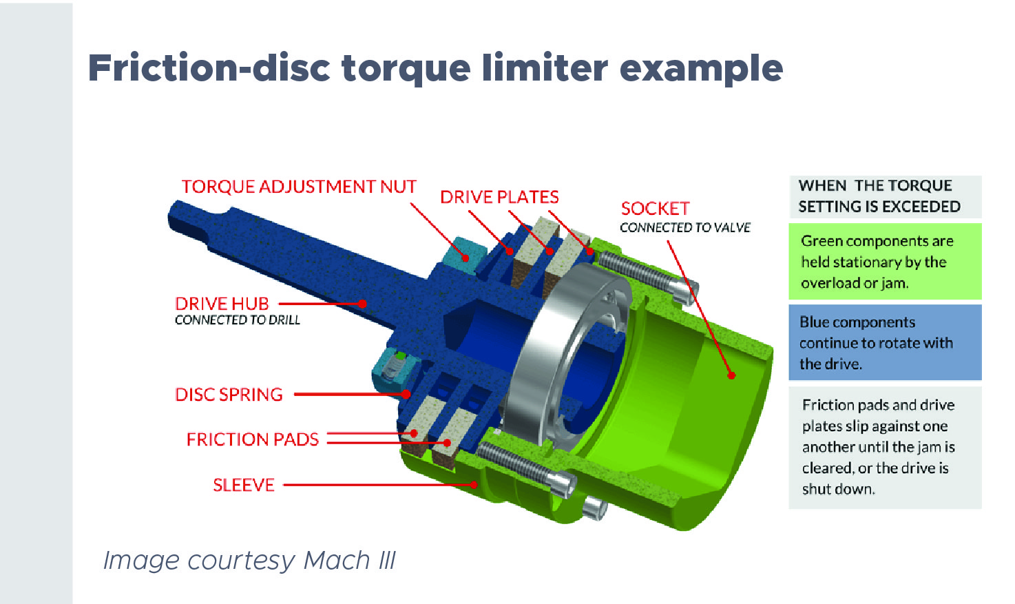
Most friction torque limiters require sensors and a means of stopping the overload condition — to prevent the torque limiter from continuing to slip and thus sustaining damage.
Torque limiters come in an array of formats to simplify integration into drives and axes of various types. Some take the form of a hub torque limiter on which a sprocket, pulley, or sheave can mount.
Some take the form of a hub with separate adapter for connection of a driven shaft to a bearing supported component such as a fly wheel.
Some friction torque limiters double as shaft-to-shaft couplings. Rigid coupling models such as this require precise alignment of the coupled shafts. Flexible coupling models, on the other hand, can accommodate a small amount of angular misalignment or parallel offset.
In fact, Mach III supplies an array or stock and custom spring-engaged torque limiters with low-coefficient friction discs to support an array of conveying, packaging, general material handling, medical, and a host of other applications.
Filed Under:Motion Control Tips


Tell Us What You Think!