


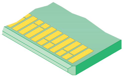
Dual Row Edge Card contacts mate with gold pads on the mating card. Image courtesy of Sullins
大多数人认为边缘卡连接器是连接器行业的尼安德特人。古老,原始和粗糙。我不同意这一点,并将向您展示边缘卡连接器的发展迅速,并且您几乎可以在每个电子设备,甚至最快的设备中找到它们。
Edge card connectors are famous for being cost effective and inexpensive for connector companies to tool. Many standards are built around edge cards, so there are a host of vendors around the world who can make them, assuring maximum competition and lowest prices to the consumer.
但是,您应该注意边缘卡连接器的某些局限性,以便在系统设计中正确使用它们。
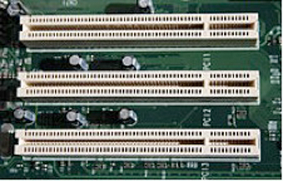
3 PCI slots in a typical PC bus configuration
图片由维基百科(Wikipedia)提供
边缘卡连接器有时被称为“一件式”连接器,因为交配的一半由印刷电路板上的黄金垫组成。这使它们最适合具有有限数量的信号路径的应用程序,这些应用程序可以适合与插件卡的每一侧的一行触点交配。过去,典型的大容量应用程序是个人计算机和服务器的附加卡。边缘卡配置特别适合主板上的轨迹连接到许多扩展插槽,特别喜欢的是。PCI(外围计算机接口)及其许多分支一直是最常见的总线系统。该标准是由Intel开发的,供IBM PC与许多外围卡连接CPU(中央处理器单元),这些卡为I/O端口提供连接,以支持打印机,无线链接,图形卡,声卡,磁盘驱动器等。
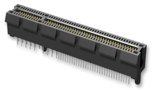
PCI Express Connector
Photo courtesy of Samtec
平行总线体系结构要求并行轨迹上的所有信号位在接收器读取之前到达接收器。该要求要求一组内的所有信号路径尽可能接近相同的电气长度。可以控制这一点越精确,需要的时钟周期越少,并且数据速率的速度越快。
布局也非常简单,主板的单层上有许多并行信号路径。这样的系统的关键优势是打印电路板可以很简单,并且不需要多层。这些卡和主板可以使用6-8个信号层设计,使成本低。公差也很慷慨,这使得这是大量低成本商品产品的绝佳格式。
跨多个扩展插槽的公交平行轨迹确实限制了系统速度。在每个连接器中“ TS”从公交车上“ TS”创建一个电源存根。该存根将能量反映回到公交线上,降低信号完整性并创建串扰。传输和接收半导体旨在处理这种更高的干扰水平,但确实限制了系统的整体传输速度。例如,PCI是32位或64位的总线结构,最初以33 MHz运行。多年来,这种平行的架构已发展为PCI-X 2.0的比特率最高可达533 MHz。只是为了使您校准,今天的串行架构的比特率在25 Gbps的范围内,因此您可以看到公交结构很慢。一辆64张宽的公共汽车需要64个信号销和其他销钉,用于接地,控制信号和电源,使这些边缘连接器长,吞噬了宝贵的主板空间。
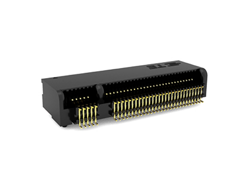
TE M.2 NGFF (Next Generation Form Factor) right angle edge card connector further shrinks the edge card form factor.
To deal with these limitations, the industry, lead by Intel, developed a serial version called PCI Express which kept the edge card format, but uses serial lanes, composed of two differential pairs, one transmitting, the other receiving. Unlike the PCI where a conductor touches each slot, the PCIe traces get an express route directly from the transmitter to the receiver without touching any other slots. This cleaner signal path enables the individual pair to operate at higher frequency, increasing bandwidth. At the connector interface, each signal pair is flanked by a pair of ground pins, further electrically isolating the signals and controlling crosstalk.
PCIe 4.0 now offers 15.7 Gbps per lane, supporting the high performance needed for today’s servers. One nice thing about this kind of serial architecture is that this physical structure can serve not only PCIe, but other serial architectures like SATA and USB as well. Specific pairs can be designated for the mix of protocols that best serves the system requirements.
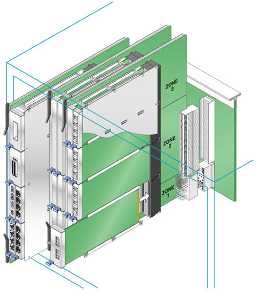
多达八张标准AMC(高级夹层卡)可以将其加热到标准ATCA卡中。
刀刀布林克霍夫的图像
传统上,边缘卡连接器与垂直于主板的扩展卡配对。由于PC已被笔记本电脑(如笔记本电脑)所取代,因此我们现在经常看到配备与主板平行的水平膨胀插槽的直角边缘连接器。功能与垂直边缘卡连接器相同,但对移动外形效果更友好。
《外国人侵权索赔法案》(高级计算机Architec电信ture) from PICMG (PCI Industrial Computer Interface Group) uses this edge card concept in a right angle configuration to support AMCs (Advanced Mezzanine Cards). These electrically tuned connectors are designed to support 25 Gbps, supporting nearly every high speed IO interface using a convenient card about twice the size of a credit card. This versatile interface now supports processors, IO, storage (either semiconductors or rotating disk drives,) and banks of DSP (Digital Signal Processing) chips that enable modern telecommunication systems with sophisticated functionality in a convenient, flexible form factor. AMC cards can be hot swapped, not interrupting system functions as cards are added, removed or upgraded in the field by untrained operators.
The AMC standard has uniquely designed gold pad configurations to facilitate this hot swap. By splitting gold pads, they are able to achieve three mating levels for ground, signal and enable functions.
Advanced MC cards split pads for sequenced mating. Image by Cleaver Brinkerhoff
从机械上讲,边缘卡连接器确实还有其他一些限制。因为您正在与插入卡上的金色垫子交配,所以循环寿命通常比两件式连接器要少,其中金属销或叶片搭配在交配连接器上带有精美的金属弹簧。通常使用边缘卡,在连接器的使用寿命中需要少于200个交配周期。
The second limitation of edge cards is that the mating PCB thickness is limited. An edge card designed to mate with a board that is 0.062 in. thick, for example will not work with a thinner 0.032 in. or thicker 0.093 in. board. PCIe and AMC cards are limited to 1 mm (0.040 in.) thick cards. This limitation dictates the number of signal layers on the pluggable card. In contrast, 2 piece pin-and-socket connectors allow thick or thin boards to be used in the same slot.
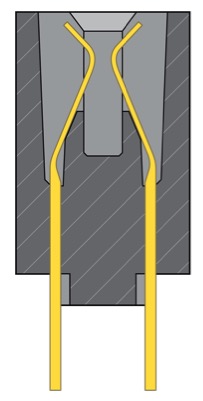
典型的悬臂边缘卡接触梁提供了温和的交配界面。刀刀布林克霍夫的图像
边缘卡连接器的第三个限制是长度/密度。由于它是一个双行连接器,在添加触点或车道时,在插件卡的每一侧都有一排触点交配,因此您需要具有更长的连接器主体。例如,PCI 120引脚连接器以85毫米长(每英寸约12对)为顶,PCIE X16连接器长89毫米。这些不是密集的连接器。
作为比较,传统的背板连接器可以提供每英寸连接器长度的40-80对差速度。可以压缩边缘卡上的接触音高。多年来,PCI和其他协议的标准边缘卡使用1.27毫米(0.050英寸)音高。PCI Express形式最初已将音调收紧到1毫米,后来引入了具有0.8 mm版本的PCIE Gen 2,甚至M-2连接器家族的PCIE Gen 2,甚至在0.5毫米的螺距上。
设计变更的需要实现finer pitch is to change the orientation of the contact in the slot. The older edge card connectors mated on the flat, smooth side of the contact. This configuration provided a gentle spring and the mating point was formed into a smooth dome, ensuring long mating life. These contacts were typically all stamped from a single strip of material in a simple, high-speed die. Stations in the die form the strip into the final contact shape. A strip of contacts could be mass inserted into the plastic housing in one motion, making these connectors simple and cost effective to manufacture.
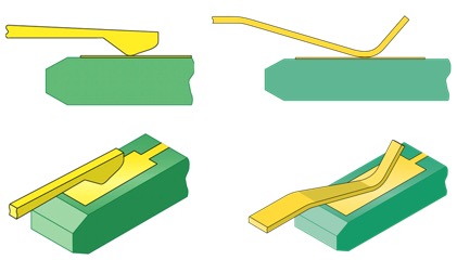
甜蜜侧的左和固定的接触式接触式接触搭配。
Illustrations courtesy of Cleaver Brinkerhoff
为了达到更紧密的音高,另一种制造方法进化了。触点被遮挡,然后一次缝制到塑料中,一次或两个,将剪切的边缘交配到卡片上的黄金垫上。这种配置会产生更僵硬的弹簧,并且在模具中需要附加涂料,以确保接触式与黄金垫平稳配合。这似乎是一件坏事,但实际上,电气性能变得更好,因为相邻的触点可以在电宽方面与微分对两个触点之间的空间中实际流动的能量相结合。通过指定信号对之间的一个或两个引脚作为地面,串扰降低,信号可以以较高的数据速率运行。
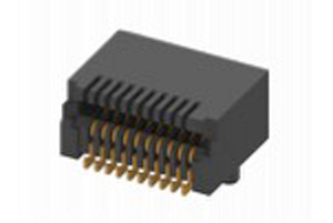
SFP connector and cages enable front panel pluggable modules
Image courtesy of Leoco
边缘卡连接器的许多不同配置使用了缝合,空白和固定的接触方法。这些压板可以具有直角弯曲,例如,适用于用于内存卡的更紧密的音高连接器,例如笔记本电脑,相机和其他移动设备的SD卡。用于用于SFP,QSFP和其他类似格式(例如,使用的高速连接器)的高速连接器。这些连接器已调整为每条差分对最多28 Gbps性能。
因此,如您所见,多年来,古老的边缘卡概念已经发展起来,变得更加密集,更越来越快,并且具有连续的几代设计。当您意识到像SFP和QSFP这样的可插入模块现在支持最先进的光学收发器时,这些先进的边缘设计似乎将在未来继续寿命。
帖子边缘卡连接器会令人兴奋吗?appeared first onConnector Tips.
Filed Under:Connector Tips,连接器(电气)•压接技术


